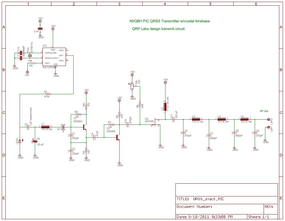
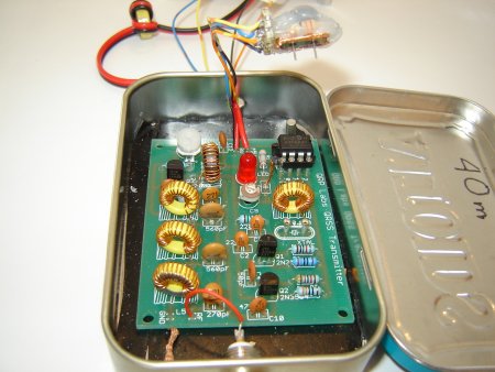
For G0UPL Transmitter Kit
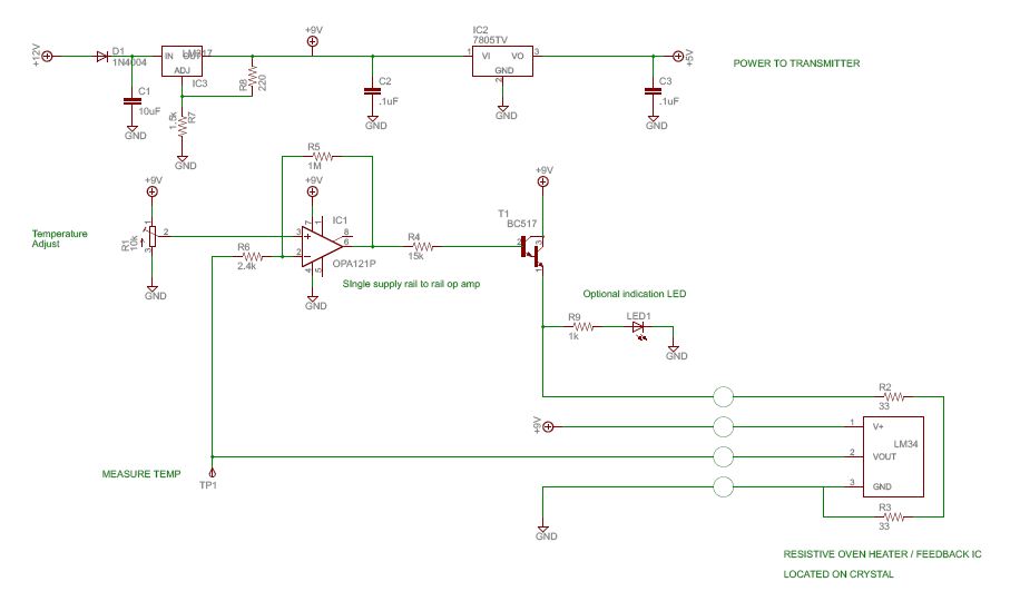
Updated schematic 9-25-11
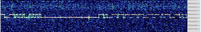
Single screen of my call (N0QBH)
After Stacking (Images courtesy of W4HBK)
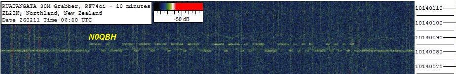
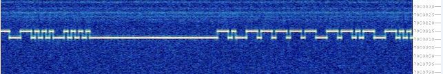
Stack of 6 Images - courtesy of ZL2IK
My 100mW copied over 8,000 miles away!
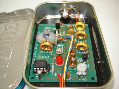
The modification is twofold. The microcontroller socket is rewired to accept a PIC 12F629 micro along with a second clock and the transmit crystal gets an oven consisting of a copper foil hat along with some hot glued resistors and a sensor.
The microcontroller handles the character timing and cannot be more accurate than it's reference.
Since the Tiny13 uses it's on board oscillator as a reference and it is at best 2% accurate, an upgrade is in order.
Frequency stability is easiest attained with temperature control.
My oven design comes from the Internet and I'm not sure who to credit other than Bill W4HBK, who gave it to me.
Here is the modified QRSS beacon
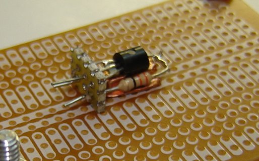
I build the oven with a crystal as the form for the copper foil, resistors and temperature sensor
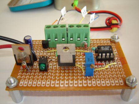
This is the power supply and adjustable crystal oven controller.
The crystal is socketed using recycled machine pin sockets.
While it's already a significant feat to send a tiny signal like ours across a continent, there are those who take this mode a step further by a concept known as stacking.
Stacking (as I understand it) involves a computer mathematically overlaying 10 min long screen images atop each other.
The random noise tends to cancel out leaving enhanced images of periodical signals.
If these periodical signals are very accurately timed and their frequency drift minimized, they will often stand out boldly above the background using this method.
With this in mind, I made some changes to my QRSS transmitter(s) and have been running modified 30m and 40m beacons for some time now.
A 32.768 KHz tuning fork clock has a typical max error of 50 ppm and can drive the 16 bit timer1 counter on certain PIC micros.
As a result, the PIC has a slow, accurate time base, yet still processes everything at it's internal oscillator speed of 4 MHz.
Now the characters are exactly 6s dot in length and the string is repeated exactly every 10 minutes.
My QRSS beacon program has a built in ASCII to Morse converter.
The transmitted call is read from the PIC EEMEM, meaning the content can be changed by advanced users.
Elegantly simple, it's quick to get to set temperature and does an excellent job of staying there.
A pair of 33 ohm resistors wrap around the crystal and a thermal sensor sits atop, all encased in hot glue.
The 10 millivolt per degree output of the AN34 temperature sensor means a VOM will directly read the temp in degrees F.
The potentiometer provides the opamp with an adjustable reference point.
Amplifier output to the darlington transistor passes just the right amount of current through the series heater resistors to drive the sensor output voltage equal to the set point.
Full version has more photos.
This page was updated 9-25-2011