60 KHz WWVB receiver modules - are now carried by Universal Solder Ebay
WWVB RECEIVER - DECODER - DISPLAY
"Receives U.S. Govt 60 KHz WWVB digital radio time standard broadcast from Ft Collins, CO"
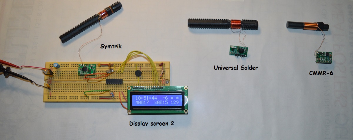
 Example with CMMR-6 courtesy of Steve Pocock KC0NGU |
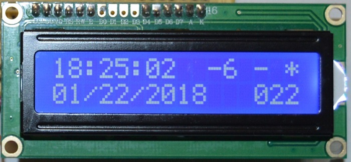
Screens One and Two with good signal |

 |
Right side of screen is timezone, next a bit quality indication and last a star when data is valid.
Horizontal bars indicate a valid bit while a < or > indicate too short or long respectively.
|
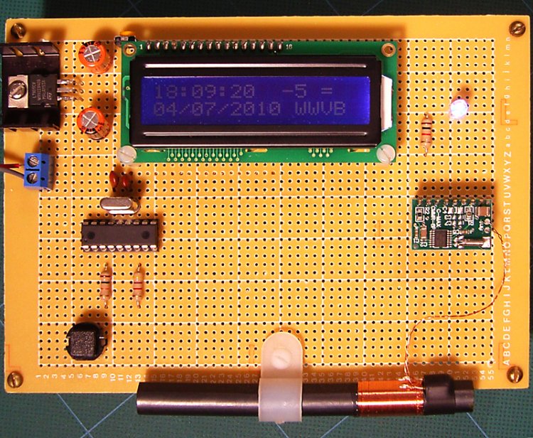
This project combines the venerable PIC 16F628A micro, one 60 KHz WWVB time receiver and a LCD display to make a very accurate clock.
The program was written in Microchip assembly language and is open source for non commercial use. Display is a 16x2 LCD with graphic signal quality and lock indication. Accuracy is within 200mS. This firmware has been tested with C-Max CMMR-6, SYMTRIK WWVB and the MAS6180C WWVB receiver from Universal Solder. New features include 4 MHz crystal oscillator to improve free running accuracy and a LED that follows the 60KHz data. 60KHz WWVB data is inverted format and receive enable low. PIC port A:0 is data, A:1 is enable.
Universal Solder, complete with a loopstick antenna for about $11. Univeral Solder Ebay
|
 |
| The signal is a low frequency (60 KHz) AM, 1 baud digital transmission broadcast from Ft Collins, CO. The carrier is modulated at two distinct amplitudes, one 10db lower in power. The high and low level pulse width ratios correspond to one of three bits: zero (0), one (1) and a frame marker. Each new 60 bit packet begins with two consecutive frame marker bits. This sequence only occurs at the beginning of the packet and is used as a synchronizer. Afterwards, a frame marker occurs every 10 seconds for the next 50 seconds before the sequence repeats. Once synchronized, the program compares the incoming data to a valid structure pattern. If any of the frame markers are missing or out of sequence, the whole packet is rejected. Next, the non data bits are stripped to form six bytes, each 8 bits wide, which contain all of the data to be extracted. Then the recovered data is stored in named variables that can be read and displayed to the LCD. For more information about low frequency radio - Wiki Low Freq |
|
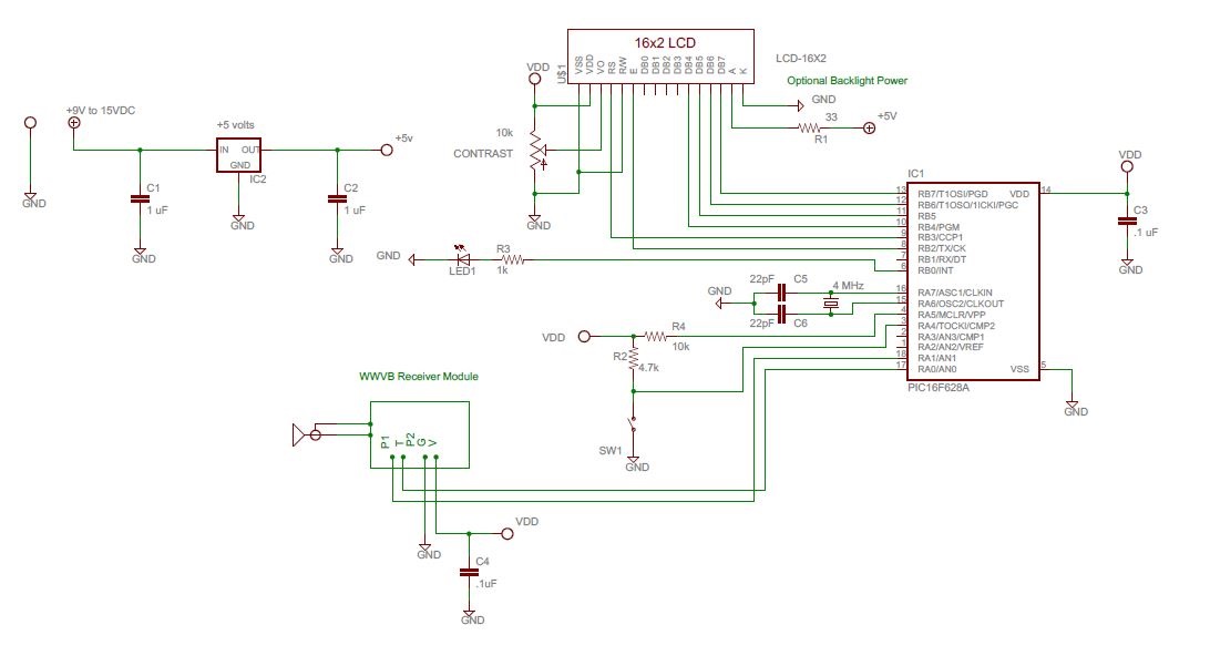
Graphic screen indication of bit reception. A LED that mirrors the receiver data output for signal optimization. Clock timing tweak to maximize accuracy when not syncronized to the WWVB signal. Screen 1 displays the date and day number on it's bottom half. Screen 2 displays good/bad minutes received and the calibration adjust on it's bottom half. FILE PACK (ZIPPED) contains firmware, schematic and instructions.
|
This page was updated 5-26-2018